Autonomous cars and mobile machines are in need of ranging sensors. In the last decades a bunch of technologies where introduced and many technological terms are used in this context: Lidar, Time-of-Flight (ToF) cameras, Stereo, Radar, Laser scanners and many more. Some of us might be confused about the sheer amount of different wordings.
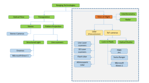
The graph below gives an overview of various ranging technologies and how they are related to each other. This article focuses on a comparison of Lidars and ToF cameras.
The principles
Principally sensors measuring the time of flight emit some kind of signal and measure the delay at the receiver. The delay is proportional to the distance of an object.
Lidars, Radars and Interferometry are a well establish technologies. Radar uses electromagnetic waves, interferometry uses coherent light, which is hard to apply on out-of-laboratory use-cases.
In previous years Lidars where only available as scanners, however this changed with the introduction of Flash Lidars. With having Lidar cameras on the market, there might be confusion about what the technological differences are.
Time-of-Flight
In general, Time-of-Flight describes a measurement principle without specific technology in mind, that is measuring the travel time of a signal and derive the travel distance. Radars, Lidars, Light modulation sensors and other technologies use this principle.
Due to historical reasons however, the term Time-of-Flight is usually applied to Lidars and cameras using as technological term.
Lidar – Emission of Light Pulses
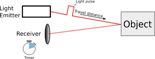
Lidar stands for Light-Detection-and-Ranging. The term is used for sensors that emit pulses and measure the time delay between emission and reception of these pulses (see below figure). The principle is comparable to Radar, however using light instead of electromagnetic waves (which is actually only another frequency domain, but let’s not be silly here).
This working principle is used in various devices, e.g.:
- 2D Laser scanners (e.g. Sick, Leutze, …)
- 3D Laser Scanners (Velodyne, …)
- 3D architecture Laser scanners (e.g. Leica Geosystems, …)
- Flash Lidars (Continental, …)
The particular implementation may vary, but the measuring principle remains the same:
Send out a pulse, detect it at receiver side and derive the distance from the time delay between emission and reception.
While conventional Lidar technology continuously scans the environment (like a machine gun), newer approaches are able to flash the entire scene with one beam and measure the time delay for a whole pixel matrix at once (Flash Lidar).
Flash Lidar might be a big leap for automotive applications, because scanning requires complicated mechanical or electronical (in case of phased arrays) technology and usually reduces the frame rate. However illuminating the whole scene introduces new systematical problems. ToF cameras have to suffer of some of these.
How are ToF cameras different from Lidars?
ToF cameras – Detecting phase shift
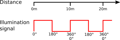
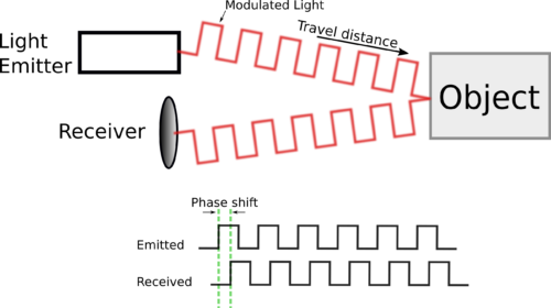
A newer technology does not use single pulses, but continuously illuminates the whole scene with a modulated light (laser or LED). The receiver integrates this signal for a certain amount of time and derives the distance from the signal’s phase shift on receiver side. The time-of-flight and thus the distance is proportional to the signal’s phase shift.
Companies and institutes call these cameras also Time-of-Flight (ToF) cameras. As we already have seen, Time-of-Flight may refer to various technologies, thus this term may lead to some confusion.
The working principle in short:
Modulate a light source and measure the phase shift of the modulation between emitter and receiver.
One main advantage of ToF cameras compared to Lidars is the much simpler pixeldesign – often realized with standard CMOS processes. Also the system integration and scalability is far simpler to achieve. Thus ToF cameras are in principle much cheaper to produce and can be easily scaled.
Following a list of some ToF camera manufacturers:
- Industrial cameras from ifm (O3D, O3X, O3M)
- Consumer cameras from PMDTec (one of the initiators of this technology)
- Mesa Imaging (one of the initiators of this technology)
- Panasonic
- Microsoft Kinect 2
Comparing Lidars and ToF Cameras
As explained above, the main difference between Lidars and ToF cameras is:
- Lidars use light pulses to measure the time-of-flight
- ToF cameras use a continuous wave to derive the time-of-flight from its phase shift.
Pros
| Lidar | ToF Camera |
|---|---|
| Better in dusty/foggy environments (does not apply to Flash Lidar) | Much smaller form factor, easier integration and miniaturization |
| Better accuracy | Lower price |
| Less systematical errors | No rolling shutter effect, range data for all pixel synchronious (applies also for Flash Lidar). |
| Usually higher lateral resolution | |
| Higher framerate | |
| Mechanical robustness (applies also to Flash Lidar or phased array Lidars) |
Cons
| Lidar | ToF Camera |
|---|---|
| More expensive | Lower accuracy |
| Usually a scan line only. Stacking of multiple devices to get 3D | Bad performance with fog and dust |
| Usually rolling shutter effect | Systematic errors due to stray light and multi path (applies also to Flash Lidar) |
| Bulkier formfactor | Lower measurement range |
| Lower lateral resolution | Motion artifacts at objects with high lateral speed. |